
Download Lab Template
Goal
Understand breadboard connections, basic use of a multimeter, and fundamentals of electronics such as voltage, current, resistance, and Kirchhoff's voltage/current laws and Ohm’s law.
Schematics, Breadboards, and Multimeters
We use schematics as a map of how parts should go together.

We use breadboards as a way to connect components without needing to solder them together.

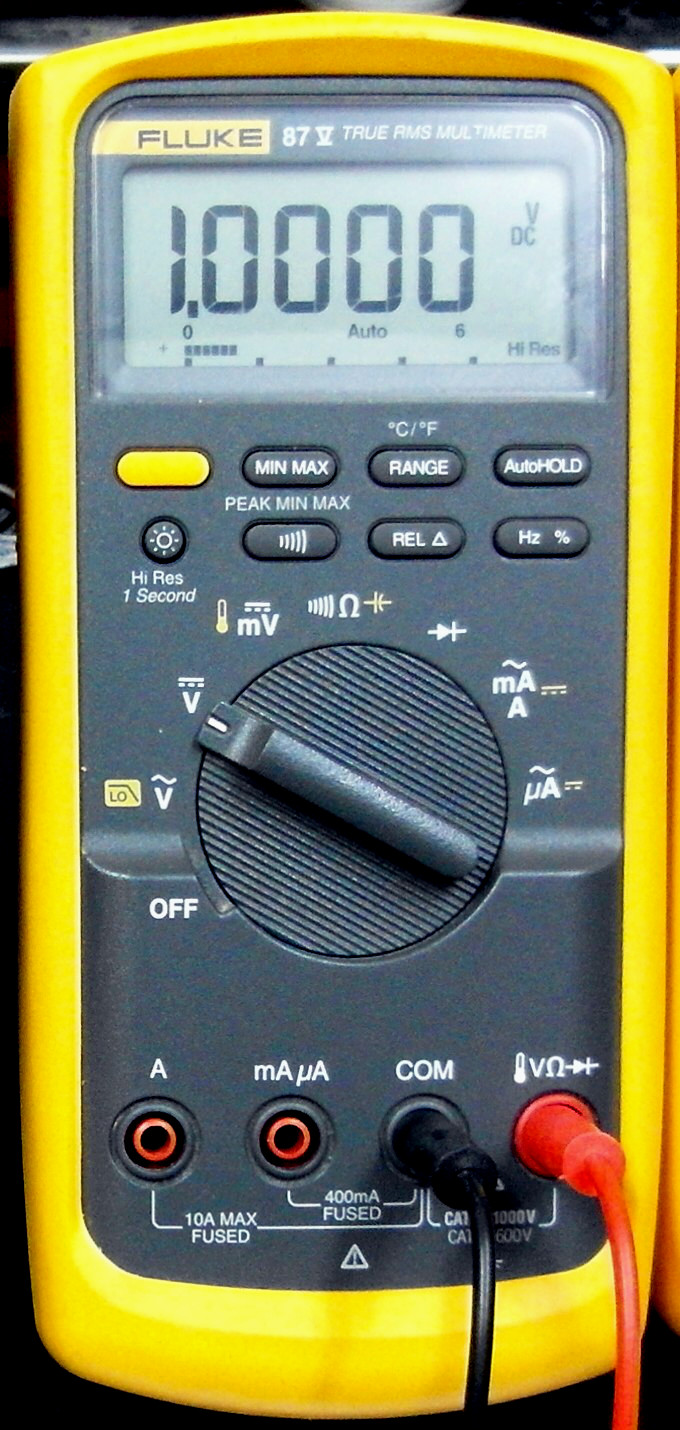
We use multimeters to perform measurements.
Source: By Binarysequence - Own work, CC BY-SA 3.0, Link
Power
The breadboard contains metal strips that connect the components for you. The outer breadboard strips, the big long ones, are used for very common connections all components need. Namely, ground, positive voltage and negative voltage. These long connectors are often called power rails for this reason.


I always connect ground to black or blue depending on the breadboard since some breadboards have different colors, and V+ to the “upper” red rail + and V- to the “lower” red rail. I also always position the board so that the V+ red rail is farther away from me. Also a good habit is to connect the ground rails with a wire. I can’t tell you how often I have made connections to the ground rails and then spent forever wondering why the circuit isn’t working only to find I never connected the two ground rails!
Note: The rails are just strips of metal! In circuits where we only have a single voltage source we will just have red and black. V+ and ground. In circuits that involve a dual voltage source we will have V- and V+. The colors themselves don’t mean anything! It all depends what you connect to those strips of metal! It is better to think of it as just 4 strips of metal rather than voltage lines.
When connecting a circuit it is important to keep these important points clear so that you don’t accidentally wire up power backwards! A very easy way to fry a chip, or at least heat it up a good amount (they can survive if you catch it fast).
I typically wait to connect power until the very end, first because the power connectors are often a nuisance to work around but also to ensure things are powered only when they are ready to be.
The Main Board
The breadboard is divided into two halves down the middle. The middle section is spaced so that the two halves are not connected. This is because the middle section is made for chips to be placed there and the chip legs should not electrically connect. These chips are called “Dual In-line packaging” or DIP for short. You can see this in the simulation above.
Many other components are also made to sit in this gap, such as the switches. The switches connect a piece of wire when pressed and fit nicely across the gap. Do not force the switches into the main area as you will bend the legs as you do so!
Following a schematic is easy with a system. I typically start with the battery and work my way around the circuit. As you get to more complex builds, considering where larger pieces will go becomes very important! Often parts on a schematic that appear to be far apart are actually part of the same chip physically and parts that appear close may actually be very large or very far apart! You will get a better sense of this as you build more circuits.
A Basic Build
To start let's consider a basic resistor circuit:

The schematic shows us some key parts, a battery (labeled), wires (in green), and a resistor (labeled as R).
For the battery by convention the longer side is understood to be the positive side. It is labeled by this symbol but several other symbols exist and some do not explicitly put a “+” sign. You will find this a commonality for many components. The short side is the "negative side".

Wires connect parts. We will use jumpers for this job. They have an extremely low resistance (ideally 0) and because of this allow electrons to flow easily.

Finally we have a resistor. Resistors come in many shapes and sizes. They are 2 terminal devices that provide a specific resistance.

Source: David Ludovino, CC BY-SA 3.0, via Wikimedia Commons
Building the circuit
We place the battery leads first. We do not put the battery in yet (the pic shows the battery, ignore that), we will do that at the end since we want to keep the circuit powered off until we are ready. Since this circuit is extremely simple we only use 2 power rails.

Checking the resistor
Next we place the resistor. First we must ensure the resistor value is the correct one. Lets assume the resistor is 1KΩ. There are two ways to do so. The first is through the color code.

Source: Knarfili, CC0, via Wikimedia Commons
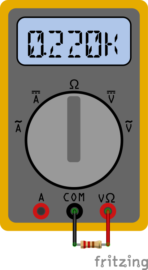
Using this chart you can check the color bands. However no resistor is totally accurate and it can be very easy to mess up the reading of the color code, therefore I encourage you to always measure it. Simply take out the multimeter. Make sure the red lead is in the V slot (red) not the amps (A) slot and place the black lead in the ground slot (black). Now turn the dial to the ohms setting, sometimes called R or resistance. This sets up the meter to measure resistance. Next place the metal of the leads across the resistors and watch the number. Keep in mind the meter will show a K for kilo meaning 1000, so a value like 220,000 will appear as 220k. A value such as 2210 can appear as 2.210k. (Not all meters use the k and just have a decimal movement). Some meters have different resistor amounts you can measure. For those meters pick the value above the one you are measuring. For example if you are measuring 1k, then pick 2k on the meter. If you pick a higher value the meter may show decimal movement to reflect the higher value it's trying to measure. For example, measuring a 1k resistor with a setting of 20,000 will change the measurement from 1000 to .1 depending on how the meter works. If you try to read a value that is higher than your setting the meter will not be able to produce a correct value. More expensive meters take care of this automatically for you.
Now that we have ensured we got the right resistor (your measurement should read 1KΩ) we must place it on the board. This process should not be forced. Remember the insides are like little clips, so sometimes we must wiggle the leads a little to open the clip. Some clips don’t align with the holes of the breadboard which can be frustrating and create not so great connections. This can sometimes cause frustration. Cheap breadboards can be a nightmare to work with.
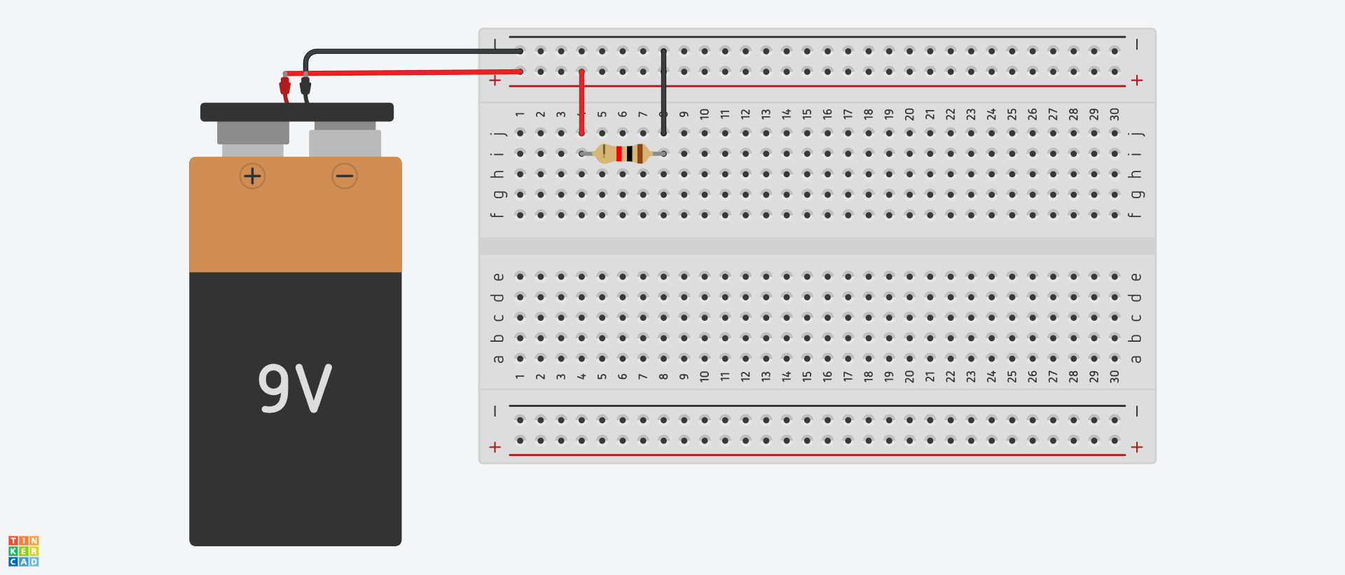
Remember, we need the resistor to be across two connections, it is very common for students to do something like this:
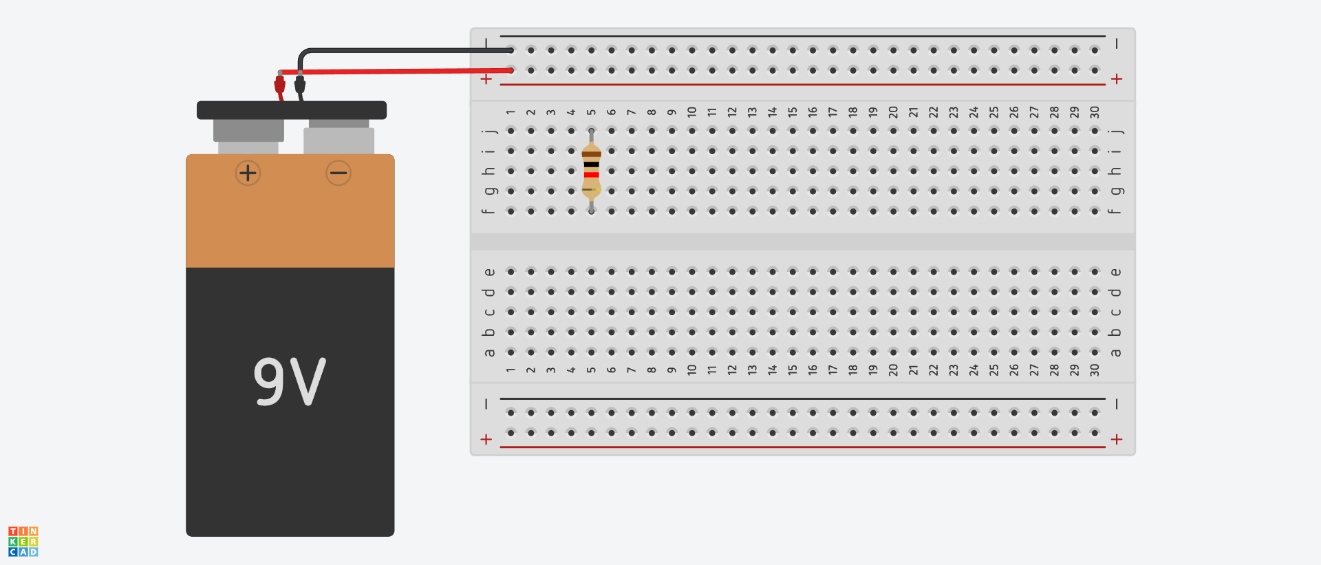
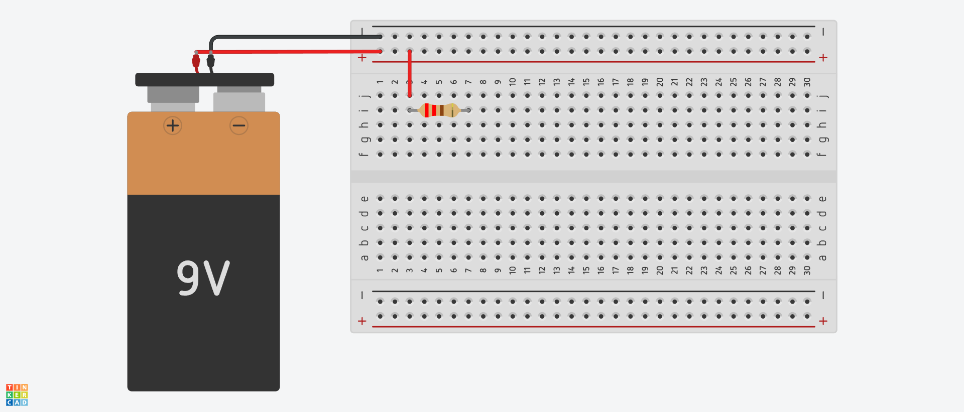
The problem with this is the resistor connects to itself through the breadboard! Here the resistor is shorted, so no current will go through the resistor! The reason is you can view the resistor as a street with a ton of traffic. Why drive through such a street when you can just skip it all together by going through the breadboard instead? Instead we should place the resistor like this:
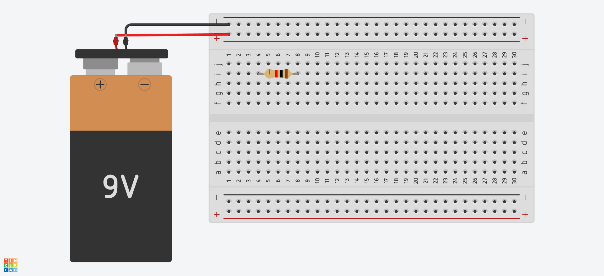
There are other ways (better ways in my opinion) but we do it this way for now so be extra clear about connections. Now the resistor is connected to two independent strips of metal. There is no longer a path through the breadboard that directly connects the resistor to itself. Now we now need to connect it to the positive and negative terminals of the battery. To do this we use jumpers.
We could connect the resistor directly to power but for now I will use jumpers to make it clear. When we make bigger circuits you will find it better to connect the resistors to the terminals directly to reduce how many jumpers are used.
Resistors do not have a polarity so it doesn’t matter which side of the resistor is connected to + or -. Parts such as diodes or capacitors do have a polarity as we will see in later labs.
Now that all the parts are connected we can place the batter in the clip and power the circuit! We won’t see anything happening, but if we take the multimeter, change the dial to V with the leads in the same place as before and place it across the resistor we will find that indeed 9V shows up across the resistor! If you unplug the battery you will find it drops to 0! Congrats you have just breadboarded your first circuit!
LED Circuit
The LED circuit is a circuit that lights up. LED’s are extremely easy to burn out, therefore please do not attach the power until after all the pieces are in place.

First again we attach the battery clip. Again we will only use 2 power rails since this circuit is very simple. With that done we will follow the positive terminal across the schematic. We see the resistor is next so we attach that and make sure the resistor is correctly attached to the positive terminal through a jumper. Also ensure the resistor is a 220Ω resistor!
Now we add the LED. LED stands for light emitting diode. Diodes allow current to flow in only one direction, a light emitting diode lights up when current flows through it. Because current only flows in one direction the diode is said to have a polarity, meaning the way we put it in the breadboard matters. It will also only light up when current flows through it in the right direction because it won’t let current pass going the other way. You can see diodes as a sort of electrical “one way valve”.
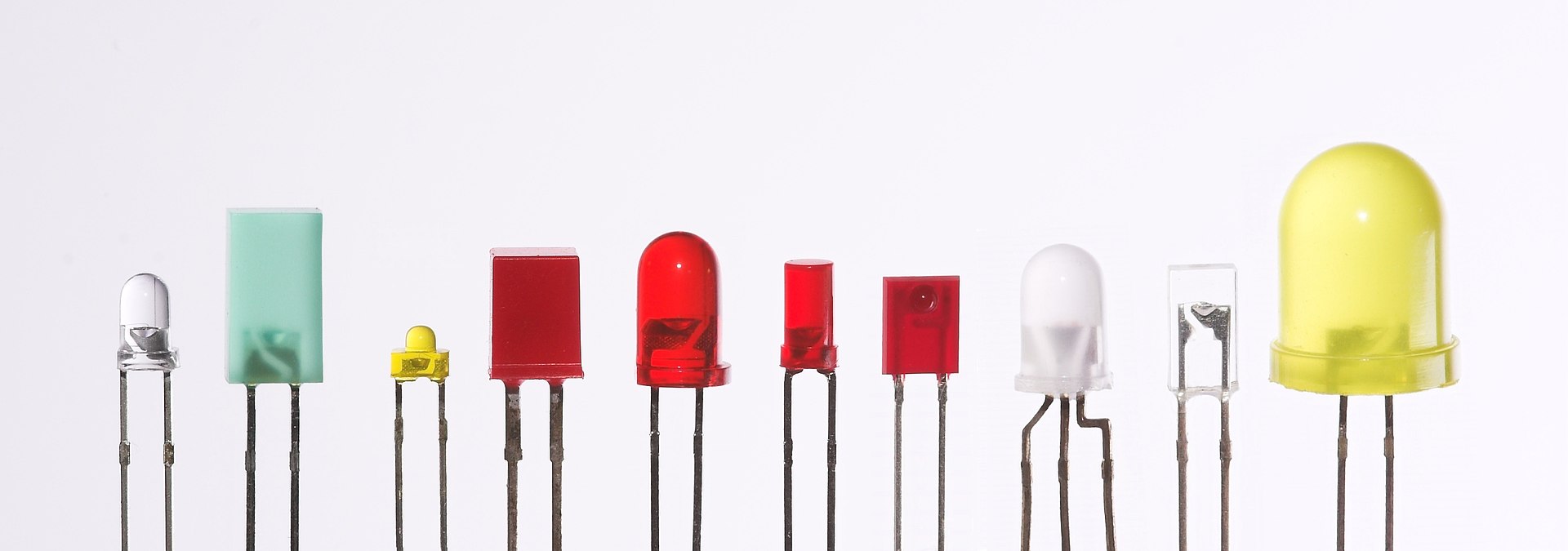
Source: Afrank99, CC BY-SA 2.0, via Wikimedia Commons

Source: Inductiveload, Public domain, via Wikimedia Commons
.svg)

Source: CC BY-SA 2.5, Link
The anode needs to be on the more positive side and the cathode needs to be on the more negative side. The longer leg is the anode meaning the positive leg. The short leg is the cathode meaning short side. The arrow on the schematic shows the direction of flow so the positive side is before the arrow and the negative side is after the arrow.
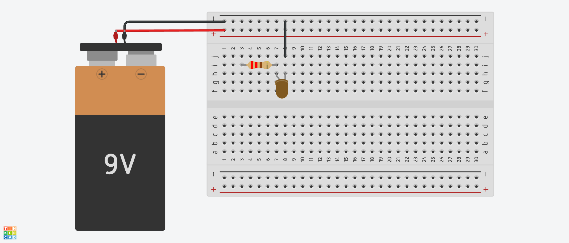
According to the schematic the anode should be coming from the same node the resistor is attached to and the cathode should be going to a new node therefore we connect it like so:

Here the bendy leg is the anode (the long one).
Finally we attach the final jumper back to the negative. The LED is a “current hungry device” meaning it will take as much current as it can handle. This means if there is no current limiting resistor in the way the LED will take all the current it can and burn out. Image its like a person who always eats whatever is in front of them. Without someone to limit the amount of food put in front of them they will eat themselves to death! For LEDs this happens very quickly, usually you see a small flash or flicker, other times it happens so fast you don’t see anything. This is why the resistor is so important. Higher values of resistors limit the current more so the LED won't be as bright, lower values of resistors let more current through and make the LED brighter.
Now with everything ready for power we can connect the batter and see the LED turn on!
Adding a switch
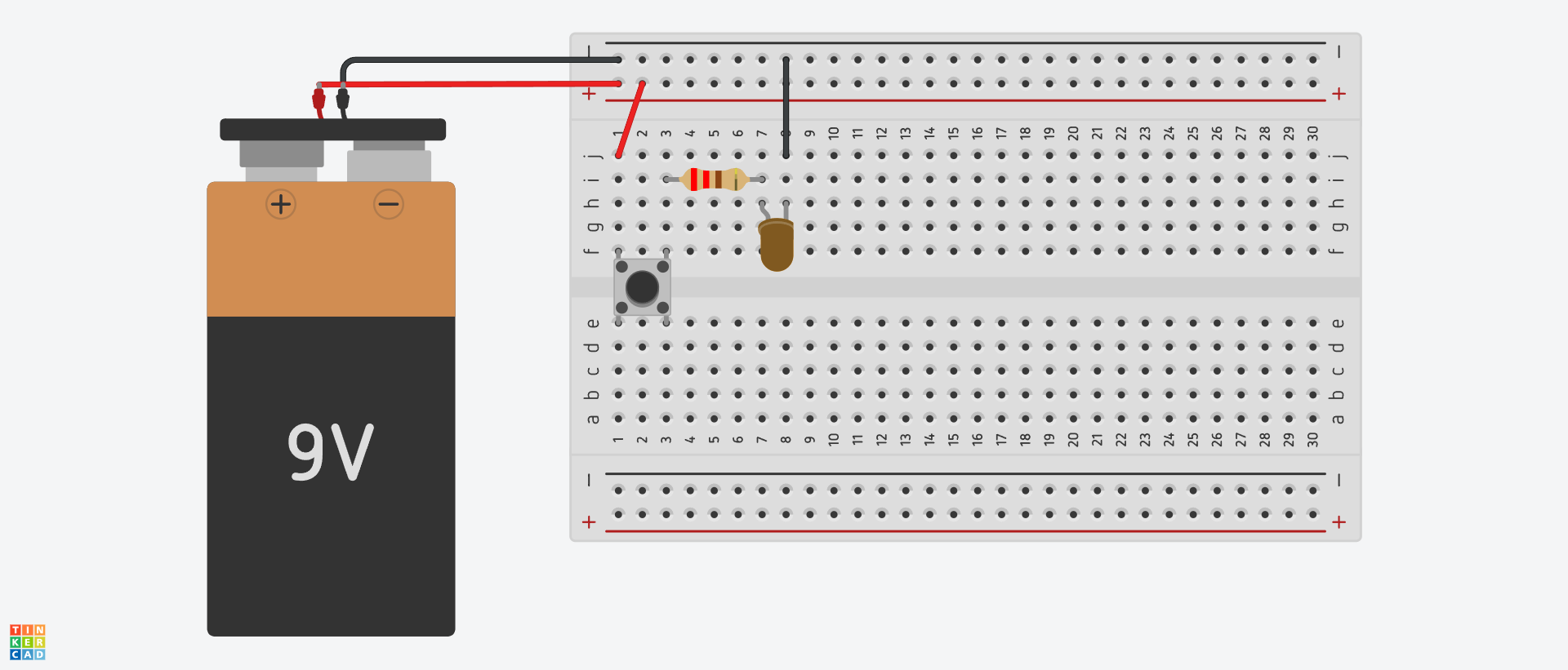
Let's add a switch so we can control when the LED turns on. We will place the switch before the resistor so our schematic becomes:

Now let's add the switch to the breadboard. Let's disconnect the battery before we do anything else. First we break the connection from the resistor to the positive rail since it will now go to the switch:
Now we add the switch. The switches are made to go nicely across the gap of the breadboard. Do not place them elsewhere as you will bend the legs. When the switch is pressed it will connect the two sides. It can be a bit confusing because the switch is a square but both sides will be connected when pressed. Now attach the other side of the switch to the resistor and boom! We have a light switch once the batter is placed in again.
Lab Design Questions 1
Must be done in class!
Submit a picture of each working (lights are on) design on the breadboard. You could include off and on states if you want to be fancy. Be sure to include the current limiting resistor we talked about before or you will burn out the led! You may work in groups.
- Design a circuit that turns on 2 LED’s with a single switch.
- Design a circuit that uses 2 switches to turn on the LED. Only when they are both pressed should the LED turn on.
- Design a circuit that uses 2 LED’s and 2 switches. Each LED should be turned on by its own dedicated switch.
- Design a circuit that uses 2 LED’s and 2 switches. Each switch should turn on both LEDs.
The Notion of “Electronic”
When we say something like a clock is electronic, or that a computer is electronic we simply mean that it does its job by using an electronic force.
This force can be used to power lights, phones, speakers and so on but when applied with the notion of signals it can become much more than just a force. A signal is a medium whose behavior contains a pattern that contains information.
(A more proper definition of signal would be how one variable varies with another.)
For example, a very common signal example is a voice. When speaking, you create air pressure waves. The variations in these waves is itself a signal. If these waves were to hit your ears you would hear them and your ear would convert the pressure waves into electrical processes by using mechanisms in your ear. It is at this point your brain gets an electrical signal and it can process that signal to get the information in it so you can “hear” them.
Note that the pressure waves themself are not the signal, it is the way the pressure waves vary that have the signal in it. If you were just given pressure waves it would be meaningless without a way to convert those waves into something we can understand. All that is needed is a medium and information.
Electrical signals have two key components that this variation can occur in. They are voltage and current.
Electronic devices work by having electrons move about in them, similar to how air moves. Air by itself just randomly bounces about, there is no information in it. It is not until someone speaks in the room that information is introduced and by extension the air is no longer random. Instead it now contains information, it has a signal.
Electrons exist in wires and they randomly bounce about, but by connecting it to a source of information the electrons no longer randomly bounce about but instead now move in a way that reflects the information.
Computers, phones and other computing devices use electronic forces, but they also use signals to do their job. Destroy the signals and you destroy the device's function.
Analog and Digital
There are two types of signals we should understand. They are analog and digital. Analog signals use a medium who can assume any value. They are not limited to say only whole numbers. They could be 1, 1.23, 1.342423, 1.234545345323 and so on. Digital signals however cannot do this. They are limited to a range, say for example it can only be a whole number between 1 and 10. Such a system would be unable to represent a value such as 1.23.
Analog “gear” has a continuously variable voltage and that can assume any value. Many people claim there is a special “sound” to such gear because of this property. Other pieces of gear such as a computer and by extension any software is inherently digital. However digital systems have become extremely advanced and are capable of producing results that are often indistinguishable from their analog counterparts. Many pieces of gear are also mixed, some parts use analog signals and other parts use digital. Calling such a device strictly analog or digital isn’t exactly accurate.
Here for example is a picture of a wave form. At this scale it looks very analog. It appears as though no information is missing, it looks like it is a continuous line that maps the amplitude of the sound.

However if we zoom in we see a very different picture:

Instead we see it is indeed a digital signal! It is actually a series of points! If it were analog you could zoom in forever, there would be no “max zoom level”.
Digital and analog get mentioned quite often and now you should be able to understand some of the basic differences between them.
Wires
When dealing with electronics we connect parts together with wires. These wires we assume are ideal. This means that they have no resistance and affect the circuit in no other way other than giving elections a path from point A to point B. This is usually a fine assumption for the real world. (Transmission lines are an example where this assumption is no longer good.)
Wires on a schematic are represented by lines.
NOTE: I will be using the software KiCad for most of this schematic visuals. It is a software for making schematics and can be used all the way into full production. It is completely free and open source and I recommend recreating these circuits yourself in the software. Other tools, both paid and free, all use similar conventions for schematics.

Here this schematic is somewhat useless since it is only a wire. These lines however will connect all the parts, if two parts are connected by a line they should share a connection, often by a wire but sometimes by other means (such as a solder joint).
We use wires because they offer a low resistance path (ideally 0) for the electrons to go from one part to another. The wire of itself is typically copper and has many electrons that move around randomly in it until a signal is present.
Current
Current is the movement of electrons. Before we can really talk about current we must talk about electrons. Electrons are negatively charged particles. They can bunch up into concentrated areas and can flow in a direction. This rate of flow is referred to as an Ampere. It is similar to how we can measure the amount of water passing a point and call that a current.
In order to measure water current we need a way to measure the amount of water that passes a point, similarly to measure electric current we need a way to measure the amount of “electricity” that passes a point in a set amount of time. To do this we use electrons and specifically we use the charge of the electron.
Electrons have a negative charge and this is something that we can measure. Similarly protons have a positive charge and neutrons have a neutral or “no” charge. There are various devices to measure the amount of negative charge but the main one we use is a multimeter. A multimeter is a device that allows the electrons to pass through it and can measure how many electrons that is.
An ampere is in units of coulombs which is the unit of charge. This is because measuring a single electron was not possible when these discoveries were happening, so a quantity of charge had to be used. An ampere is 1 one coulomb of electrical charge moving past a point in 1 second.
Electrons have a negative charge and we can quantify such charge. The unit of charge is a coulomb. The coulomb is defined as the amount of charge that passes through a conductor that carries 1 ampere per second.
Amperes are shortened to Amps often. We will be dealing with very small amounts of amps in this class. Nothing dangerous, as we will also be low voltage. You will see milliamps or mA often, this means 1 thousandths of an Amp. It is on this scale we will often be working, or in other words 1 milliamps is .001 of an Amp.
The Cause of Current
Current can be described in two ways.
- Electrons flowing in a direction
- The “holes” the electrons “fill” flowing in the other direction.
This stems from the simple law that particles with the same charge repel. Likewise opposite charges attract.
Meaning if 2 electrons are next to each other they will push themselves apart because they are both negative and therefore apply a force to each other.
So a current forms when there is a charge imbalance, meaning there is more of 1 type of charge in an area than another area. This causes the charges to push apart and “flow”. In this way electrons flow away from the negative “source” and towards a positive “source”. It is very common however to follow the flow of positive charge, not the negative charge flow. Meaning instead of seeing it as current coming from the negative terminal to the positive (how electrons would flow) we instead view it as the “holes” flowing from the positive terminal to the negative, meaning we follow positive charge flow instead of the negative, or in other words the opposite direction the electrons flow in.
I don’t want to get into how this works on an atomic level because it is not needed for this class, but in short two ways of defining current exist and are both valid. Current that is defined by the positive charge flow (from the positive terminal to the negative) is called conventional current. This is the type of current we will use.

Source: User:Flekstro, CC BY 3.0, via Wikimedia Commons
Schematic Example
It is common to represent the current with an arrow as shown above. Here we see that 10mA flows through the wire from 1 place to the next as shown by the arrow. Simple right? Most of the time that is all we need to understand.

The Kirchhoff Current Law (KCL)
The Kirchoff Current Law is one of 2 laws that will prove to be used in nearly everything we do. It states:
At any node the sum of the currents flowing in must equal the sum of the currents flowing out of that same node.
You can think of it as a street system. If 10 cars enter an intersection, then 10 must also leave it. Cars can just magically vanish, and more cars can just magically appear. It is the same with electrons. If 5mA of current enters a node or “intersection” then 5mA must leave.
This is obvious with a node on a single wire.

With node on a more complex wire this must also hold true:

Here we see that 5mA enters from every side except one, so using KCL we see that 5mA + 5mA + 5mA = X mA where X is the unknown quantity. In this case it must be 15mA leaving the circuit!
See how we used KCL to form an equation? This type of equation forming is called “nodal analysis”. It is one of the fundamental forms of analysis we will use. Try it out on the following:
KCL Questions
Instructions: Solve for X. Show your equation and your answer in the report.
Question 1

Question 2

Voltage
Voltage is an expression of potential energy. For this reason it is often called “potential”. Voltage is an expression of what the electric field could do to a charged particle if it were there.
Let's use an analogy. The gravitational field. The gravitational field is really an expression of what happens to objects that are in it. Consider a bottle of water on a table. The bottle is in the Earth's gravitational field and so gravity pulls it down. The table keeps it from going down any further. Then let's say you come along and pick the water bottle up and raise it high. The bottle is still in the field and when you raised it you had to overcome the force of gravity in order to bring it up. With the bottle in the air if you let it go it would fall. But you're holding it so it doesn’t fall. In this way the bottle has “potential energy”, it would fall if it had no other forces acting on it (you holding it up) because of the gravitational field. This is called gravitational potential energy. Anything in the gravitational field will move according to the potential energy the field has at that point.
Now consider the bottle is no longer in the high position. The field still has potential energy, because if an object were there the field would act on it. This is why it is called potential energy. If an object is in the field it will be acted on but just because an object is not there doesn’t mean the field isn’t, and therefore the potential energy is there. Once an object is there the field will apply its force.
Similarly in electronics, charged particles are affected by the electric field. If a particle is in the field then it will be acted upon by the field, but if no particle is there the field itself still has electric potential. This electric potential is called voltage.
Voltage relies on there being a net positive charge in one area and a net negative charge in another and this is what causes an electromotive force or emf on the particle. Similar to an object falling due to gravity. Since 2 points are required with different charge balances we always talk about voltage across a component. It doesn’t make sense to talk about voltage at a point because then there are no positive and negatively charged regions for a voltage to form!
You can see it kind of like distance. If you're running somewhere it will take some amount of time to get there. For example you can run from your home to your neighbors and that will take some time. But it makes very little sense to ask something like “How long will it take you to run where you're currently at?” This is nonsense, you're already there! In order for your question to have meaning it must be in reference to where you are. For example, how long will it take you to run from the mall to the school, or from your home to the library? In each case a reference is given, the mall in the first one, and your home in the second. Without these references it is unclear. Asking “How long will it take Beth to run to the school?” doesn’t make sense because you don’t know where Beth is starting from! You can’t have a time if you don’t have a starting and an ending point!
Similarly a voltage must be across a component. Meaning it needs a reference. A voltage “at a point” is like asking how long it takes Beth to run to the school. If you don’t know where Beth is you can’t answer it. A voltage at a point for the same reason cannot be answered, it will always be referred to by something.
For example, say we have a resistor. Let's say the voltage on one side of the resistor is 4 volts and on the other is 2 volts. So we can say the resistor has a 2 volt drop. It's just the difference. But how can we say things like 4 volts on one side and 2 volts on the other? It’s because we define a spot somewhere in the circuit that we call “ground”. This spot is defined to be 0 volts. So relative to this spot the voltage is 4 on side and 2 on the other. There are always 2 points when talking about voltage.
For now this is the key principle. As we go further you will find negative voltage is just as valid as positive voltage. All it means is your reference is not the lowest voltage in the circuit.
So if we say something like the voltage across the resistor is 4 volts then that is saying there is 4 volts of potential energy difference from the input of the resistor and the output of the resistor. In other words if electrons are present they will be acted upon by this voltage and “pushed” through the resistor.
Kirchhoff’s Voltage Law (KVL)
Since voltage is a form of energy, and energy cannot be created or destroyed, all closed loops will always wind up with 0 volts. That is to say, energy is conserved. There are voltage sources such as batteries that provide a constant offset of charge between two terminals. The voltage the battery is rated for is given by its stated voltage. So if we have a 9 volt battery that means there is 9 volts of potential energy between the terminals.
Say we have the following circuit:
Here we have a 9 volt battery. It is not connected to anything. In this case the 9v is simply a source of potential energy, there is no wire connecting it to anything and so if you were to take a multimeter and place it across the battery you would read 9 volts. When measuring voltage with a multimeter, place the black probe in the ground slot and the red probe in the voltage slot. Then make sure you are measuring DC voltage by turning the dial or pushing the button depending on the meter, to DC volts. Most meters label this directly but the standard symbol is a line with a dashed line below it.

Open and Short
This circuit (just a battery with nothing connected) is known as open because the voltage has nothing to act on since it isn’t connected to anything. No current flows, it can’t! There is no wire for current to flow through! If you were to place a wire across the terminals (do not do this) the wire would max out the capacity of the battery to provide electrons and heat up to a dangerous level. This is because the charges from the negative terminal are attracted to the charges on the positive terminal and will flow to them. Since there is no resistance in their way they will flow through the wire easily, and in theory an infinite amount of current will flow. This won’t happen in reality because the wire offers some amount of resistance. This resistance against so many electrons will let off heat (usually unwanted except in applications like toasters and other electric heating elements) and the wire will get warm if the battery can provide enough. When two wires touch each other they will offer a very low resistance path and electrons will always take that path. Sort of like how we will drive on streets with no traffic instead of taking a road that has a lot of traffic because it is easier. Such connections are known as shorts and are unwanted.
Now consider the battery connected to a resistor as shown in the schematic:

In this case the battery has a connection but the resistor is not completing the connection. What do you think will happen to the voltage measured from the battery to the resistor? Will there be a current?
The answer is there will be no voltage drop across the resistor because the resistor doesn’t complete the loop! Therefore no energy will be used to go through it since there is nowhere to go! The resistor is open. Since there is no path available no current flows either.
You can see an open like a hose with a nozzle on it. If you were to stick a piece of foam in the hose that resisted the water flow, so that water still passed but there was resistance to it, then if the nozzle were open less water would flow due to the resistance. However if you close the nozzle the pressure “backs up” down the hose. No water flows through the resistive foam anymore and the pressure on both sides of the piece of resistive foam is the same. Meaning before in the open nozzle case there was a pressure drop because water could flow, but when in the closed nozzle case it can’t because there is no pressure drop across the foam. This is similar to electron flow through a resistor.
Note however that if you measure from the output of the resistor to the negative terminal of the battery you complete the circuit through the multimeter (which itself has a super high resistance and appears like an “open” to the circuit hence why it is used to measure voltage) and that will measure 5 volts, because it is like measuring across the terminals of the battery in this case. Say for example the resistor is only 100 ohms and the multimeter is 1,000,000 ohms. Compared to the multimeter the resistor is very small and will barely affect the measurement. Interestingly if you were to increase the resistance of the resistor to be similar to the multimeter you would find the voltage measured is no longer 5! As we get more into resistance we will understand why this is.
The concept of ground
Now consider the following circuit, assume the voltage is 9V:
Here we have a resistor. Now will there be a voltage drop? Will there be current? The answer is yes! Now there is a complete loop. The current now has a path to the resistor and back to the battery.
To understand this we must introduce a concept of ground. To do so let's consider a single electron. Let's say an electron starts at the negative terminal of the battery and call this place ground. Ground is defined to be 0 volts with reference to any point in the circuit. It is our “starting point” so to speak. We could place it anywhere in the circuit but the negative terminal of the battery makes the most sense. Now at the negative terminal the electron flows to the positive terminal of the battery. The voltage across the battery is defined to be 9 volts (in practice the voltage will be designed by 9 volts, meaning a 9 volt battery for example) and therefore we go from 0 to 9V, so we can say this node with reference to ground is 9 volts. Now each point on the wire has little to no resistance so everywhere on the wire is also 9 volts. You can imagine it like we pick a bunch of balls up in the air, they all have the same gravitational potential energy since they are all raised by the same amount.

We reach the resistor. The value of the resistor doesn’t matter for now because there is only one resistor so all the current must flow through the resistor. Further, we see the wire on the other side of the resistor goes back to the node we called ground so all points on that wire must be ground, meaning 0 volts. So that means on one side of the resistor is 9 volts, on the other is 0 volts, therefore the voltage across the resistor is 9 volts! This simple example shows how KVL and KCL can be used to understand a circuit. As for how much current flows, that is a different story and for that we must talk about resistance. Before we do so let us consider moving ground.
Again assume the voltage is 9V.

Consider the electron starting at the negative terminal of the battery and we call that node ground. Now the + terminal is 0 volts because it has ground defined to be there. The battery itself is 9 volts. Since we are at the - terminal we go through the battery and back to the positive terminal. In doing this the electron travels through the 9 volt battery. So it must be raised by 9 volts. But we have defined the + terminal to be 0 volts! This means we must have come from -9 volts! Therefore the negative terminal is now -9 volts since the positive terminal is 0 volts! Go ahead and measure this yourself now! Be sure to place the red probe at your starting point! You will find the meter now reads -9 volts! This is known as polarity and it matters!
This is because KVL holds! When measured this way the resistor still has 9 volts across it because one side is still 0 and the other is -9V. Following the path of the electron we go from a lower voltage to a higher voltage. If we measure the voltage with this view we place the positive (red) probe on the -9V side and the negative probe (black) on the 0V side. We see it now measures -9. The negative symbol lets us know that current is actually flowing in the opposite direction to what we are measuring!
For simplicity we typically put ground in a convenient place to avoid confusion, usually at the negative terminal of the battery. We won’t get much more complicated than this.
Resistance
Electrical resistance is measured in ohms (Ω) and is a measure of the opposition of current. If current has a harder time getting through then the resistance is higher. The form of resistance we will deal with is the resistor. These devices are constructed to give specific resistance values. We saw these at the start of the lab.
We will get into resistors more as they come up but they give way to an important law.
Ohm’s Law
Ohm’s law states that voltage = current x resistance or V=IR. Fundamentally we can make sense of this through a few thought experiments.
Fixed Resistance
If the resistance is held constant and the current is very big then a big force must be driving it so the voltage must also be big. Likewise if the current is small then the voltage must be small. You can see it as:
Voltage = (some big value)(R) = big voltage
Voltage = (some small value)(R) = small voltage
If the resistance can vary but the voltage is fixed (the case for many of our circuits because we will use batteries), then if the resistance is big then the current must be small and vice versa. Solving for I we get I=V/R, this makes it a little easier to see:
Current = (V)/(Some big value) = small current
Current = (V)/(Some small value) = big current
With these 2 insights resistors have 2 key properties we will use:
- They can limit how much current can flow.
- They can make voltages bigger or smaller.
So you will hear about voltage dividers and also about current limiting resistors, which are jobs resistors can do. There are many other uses but these are of key interest for us.
NOTE: Ohm’s law only applies to completed circuits. If the circuit is open then ohm’s law doesn’t apply. This is because no current flows so there is no relationship between voltage and resistance anymore. In other words components that are left open do not have voltage drops across them.
Example:
Consider the following circuit:
Consider the battery to be 9V and the resistor to be 1Kohm.
We can use ohm's law to find missing quantities. If we know any 2 things we can use it to find the missing thing. In this case we know the voltage and the resistance so we can use that to find the current.
We know the voltage is 9V and the resistance is 1kohm, and ohms law states V=IR. Solving for I we get I=V/R and plugging in we find I=9V/1000ohms and we see that .009 A of current flows or 9mA.
Ohm's Law, KCL and KVL from the foundation of circuit analysis. They allow us to form equations from known physical laws to solve for missing quantities.
Ohm's law is easy to see applied when there is only 1 resistance. When there are more resistances it becomes tricky. Fortunately there is a way to combine multiple resistors into 1 resistor.
Equivalent Resistances
Often we have many resistors and need to simplify them down to one big resistor. To do this there are 2 configurations we should be familiar with.
- Series
- Parallel
Series
Series resistance are resistors that have the same current. For example:

Here we see the resistors must have the same current flowing through them. Often exercises just have resistors and no battery. Such cases are technically open so you must imagine a battery being placed in the circuit and then ask if the resistors have the same current. Note series resistance does not depend on how it looks! It must have the same current. That is what is important, wires on schematics can be written to be curvy or straight; it doesn't matter, so long as the current is the same.
I should note here that I will use the dot convention. Wires that cross and have a dot are connected. Wires that cross and do not have a dot are not connected. This is a very standard convention I encourage you to use for clarity. There is also a bump convention but this one can be hard to do in software so I do not use it.

Resistances that are in series may simply be added up.
where
Example:
Here we see we have 3
Thus we can combine those three resistors into 1 equivalent resistor and using this resistor we could apply Ohm's law and find the current if we wanted to.
We know
The symbol with the triangle represents an Ammeter which is a device that measures current flow. We can see it correctly says
Why have multiple split resistors in series? The reason why is voltage division. We often want to split the voltage up and this can be done by multiple resistors. Each resistor must have a drop across it. We also know that energy must be conserved in a loop. This is just KVL that we talked about earlier.
Each resistor can be described by ohm’s law,
Here each V with a circle represents a voltmeter and measures the voltage across 2 points, in this case across each resistor. Using KVL we know the voltage supply must be equal to the drop across each resistor therefore:
For each resistor we now use Ohm's law.
So since all the resistances are the same they have the same voltage drop:
Drop across
Drop across
Drop across
Note that the sum of these drops is equal to the supply voltage of 9 volts! Go ahead and measure this to see for yourself! KVL HOLDS!
You can now vary the resistance of one of these by picking another resistor of a different value. You will find two results.
- The total current will change since its equivalent resistance is now different.
- You will find that the voltage drops will change as well and will no longer be equal.
I don’t want to get too much into theory but you should understand these basic laws.
Now measure from V2 to the negative terminal. You will find it is 6 volts. This is because 2 resistor drops are being measured across. So if you measure across all three you get 9V, if you measure across just the last 2 you get 6V and just the last one you get 3V. In that way you can create the voltage that you need!
Equivalent Resistance 1
Instructions: Solve for the equivalent resistance. Show your equation and your answer in the report.
Question 1

Question 2

Question 3

Parallel
Resistors are said to be in parallel if they have the same voltage. This is easy to tell because the resistors will have the same nodes connecting them since a wire has the same voltage along it.
The circles a V in them are voltmeters that simply measure the voltage. We only really need one, but I put it there to make it clear that each resistor is indeed really at the same voltage and here is why.
Here the battery voltage appears at the top node which all the resistors connect to. That entire node must be at the same voltage as the batteries, remember it is just a wire with a very low resistance. Then on the other side of the resistor they are connected to the negative terminal and again are all at the same voltage as the negative terminal. This must mean all the resistors have the same voltage across them.
So series resistance changes the voltage, parallel resistance changes the current.
Here I have 2 resistors. Are they in series or are they in parallel?

They are in parallel! The reason is they share 2 nodes and hence have the same voltage across them, in this case 0 volts. If we were to add a battery to the circuit they would no longer be in parallel because now they share different nodes, the battery would split it up.
Situations like this can be a bit confusing at first, but by using the node method and ensuring they have the same voltage then we can be confident they are in parallel.
The formula for the equivalent resistances is given as:
where
So for the simulated example we would have:
Using the total current we could use Ohm’s law again to solve for the current in each resistor.
Equivalent Resistance 2
Instructions: Solve for the equivalent resistance. Show your equation and your answer in the report.
Question 1

Question 2

Question 3

Mixed Cases
Often we need to use both series and parallel to simplify. (More complex scenarios exist that we will not cover.) For example:

Here we have 2 sets of parallel resistors in series, so we should combine the parallel resistors first and then combine them as series. We know the sets of resistors are in series because the same current that goes into the first set must come out of the second set. We know the resistors in the pairs are in parallel because they share nodes indicating the same voltage is across them.
Simplifying to pairs of parallel resistances using the equivalent resistance we reach this simpler circuit:

Finally adding in series we reach the final equivalent resistance:

Now we can use Ohm's law to find the total current flowing in the circuit. We could then use KVL, KCL and Ohm’s law to go through it and find the various voltage drops and specific currents flowing through specific resistors in the circuit if we wished to.
Lab Design Questions 2
Must be done in class!
Submit a picture and a schematic of each working design with the meter measuring the resistance of the circuit. Make sure the circuit is clearly visible. Your measurement should be close, they will not be exact. For example if you measure
Given 5
Now that you know how breadboard routing works and the basics of voltage, current and resistance we can move on to the passive mixer lab.